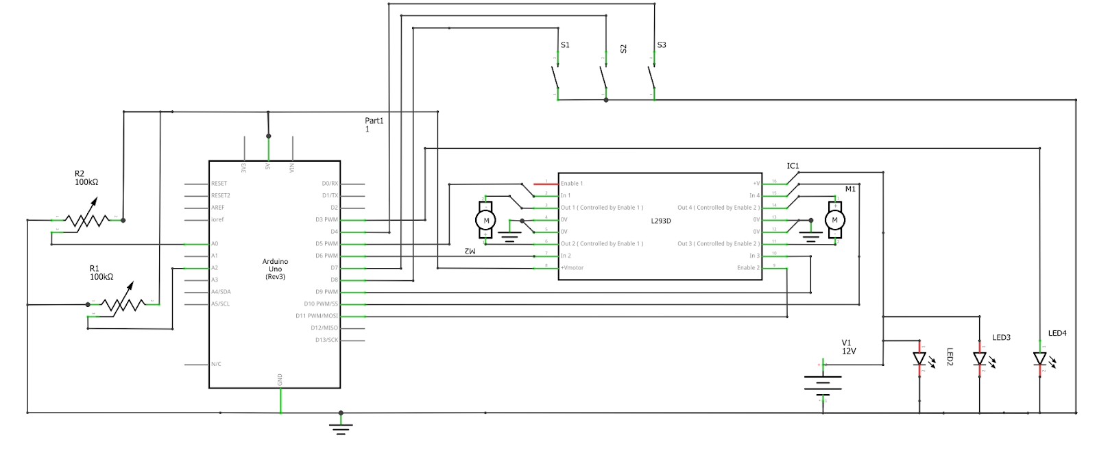
Once the mechanical design was complete, the team looked into various sensors and other electronic components that would give the desired results. Every component that was bought was first tested individually to ensure that it worked as expected. Eventually, when all the components had been finalized, purchased and tested, a circuit schematic was then designed. That schematic can be above and includes, one Arduino Uno, two potentiometers, three push buttons, 3 LEDs, 2 DC motors and a motors driver.
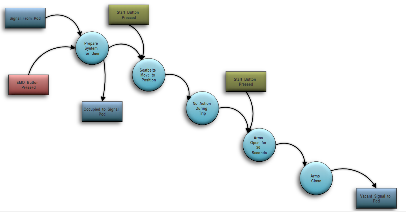
The individual sections of code used for testing were then integrated in order to create a program that follows the flow diagram seen below. Once the code was complete the entire system was then put through systematic testing to ensure everything worked as desired. The team then proceeded with monkey testing to ensure the system was free of bugs.
Lastly, the system was then integrated with the mechanical assembly and tested once more to ensure that everything still worked after being connected for the final time.
Comments
Post a Comment